

Draw the diagram
Open it: in the Roof Design editor, choose Open SLD from the downloads toolbar. You can also use the standalone editor at/sld.When you open it from a roof design, it loads with the inverter you configured, its MPPT inputs, and the strings you built. If you have not configured an inverter yet, the canvas opens empty.- Set the supply with the Phases buttons.
- Drag components from Components onto the canvas — or click one, then click where it goes.
- Drag between two terminals to run a cable.
- Select a cable to edit its route, or to rename it.
- Select a component to open Object properties — label it, set its model and rating, and open its INTERNAL COMPONENTS.
- Choose Download PDF to export the drawing.
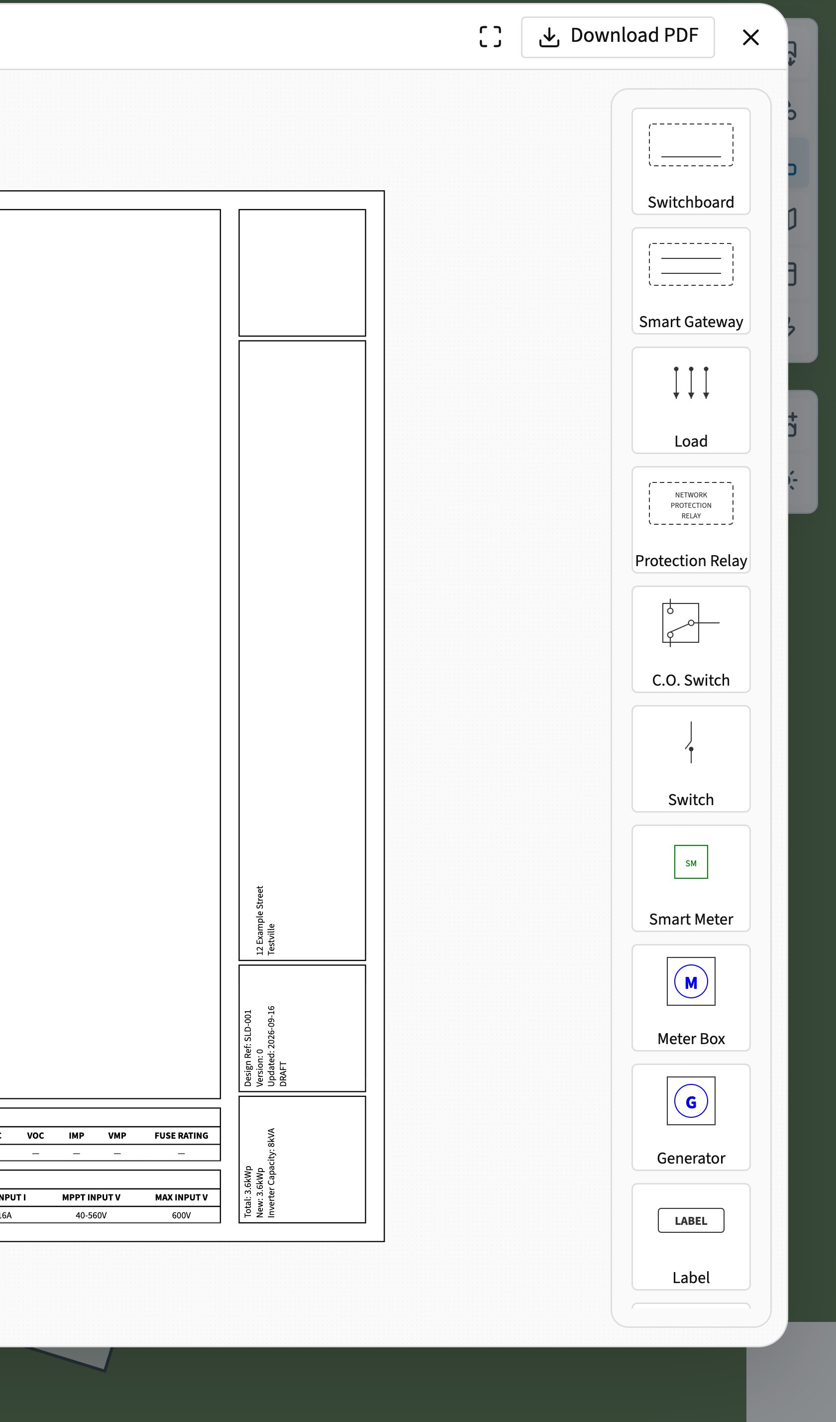
Standalone design build from a synthetic roof design; the diagram is built from the roof equipment. The Components palette lists the eleven entries, from Switchboard to Legend — the list scrolls, so the last entry sits below the fold. The wider symbol catalogue is drawn inside assemblies such as a switchboard or the Smart Gateway.
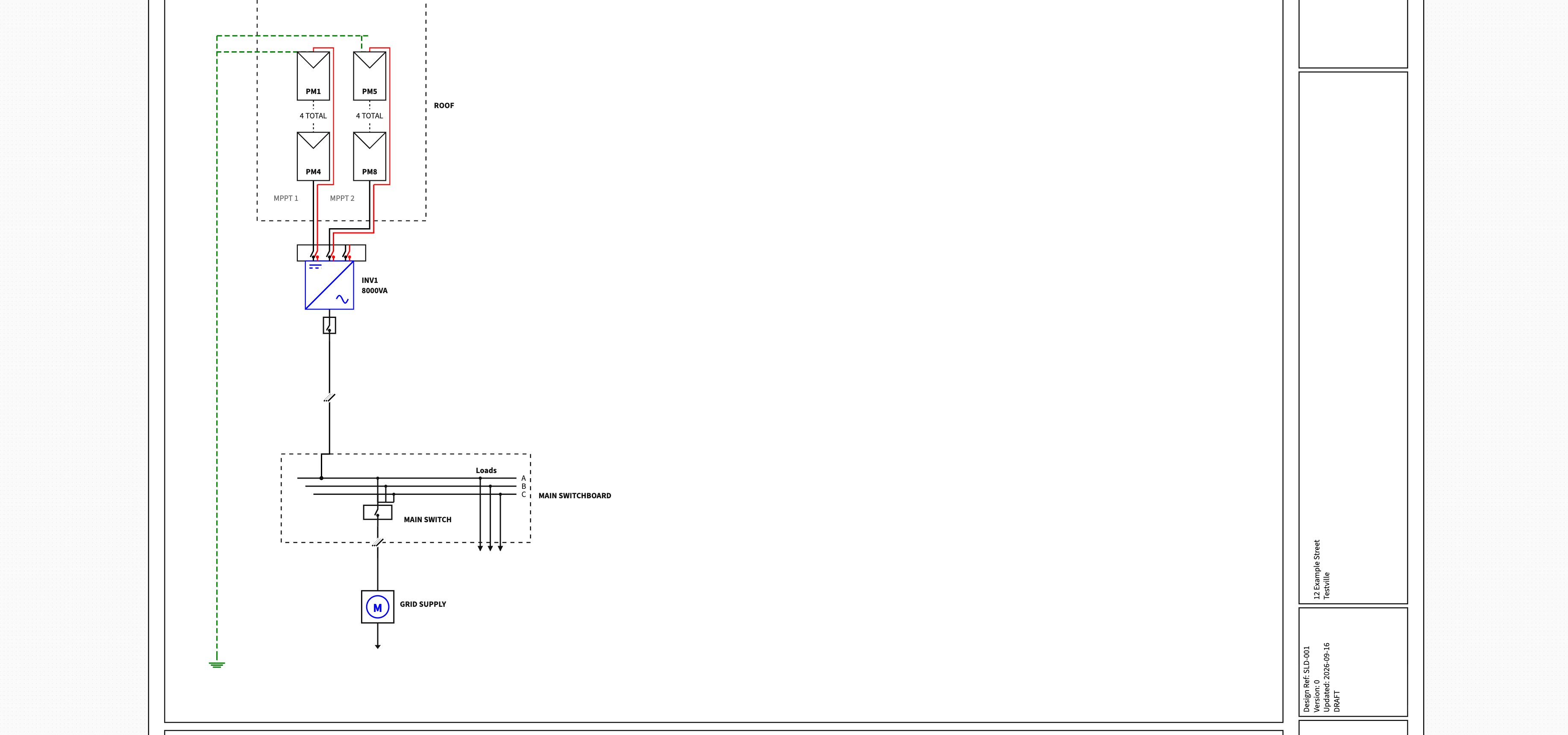
A diagram seeded from a roof design, shown on the project sheet. The inverter keeps its project identity — INV1, 8000VA — together with its MPPT inputs and the module groups assigned to them; the switchboard carries its own internals. Crossing lines are not connections — only a dot joins conductors.
- Every cable joins a terminal on one symbol to a terminal on another. A line that crosses another line is not a connection — only a dot is.
- DC and AC are kept apart. An AC terminal will not accept a DC cable, and a communications or metering terminal will not accept a power cable.
- Every circuit you need has been drawn. The editor checks what you declared; it does not know what the site actually needs.
single-line-diagram.pdf. Opening from a roof design gives you a one-page A4 landscape project sheet with PV MODULES and INVERTERS schedules. Larger drawings are exported to A3, and a drawing too big for one A3 page is split across pages. The editor also exports its drawing as SVG through its embed interface.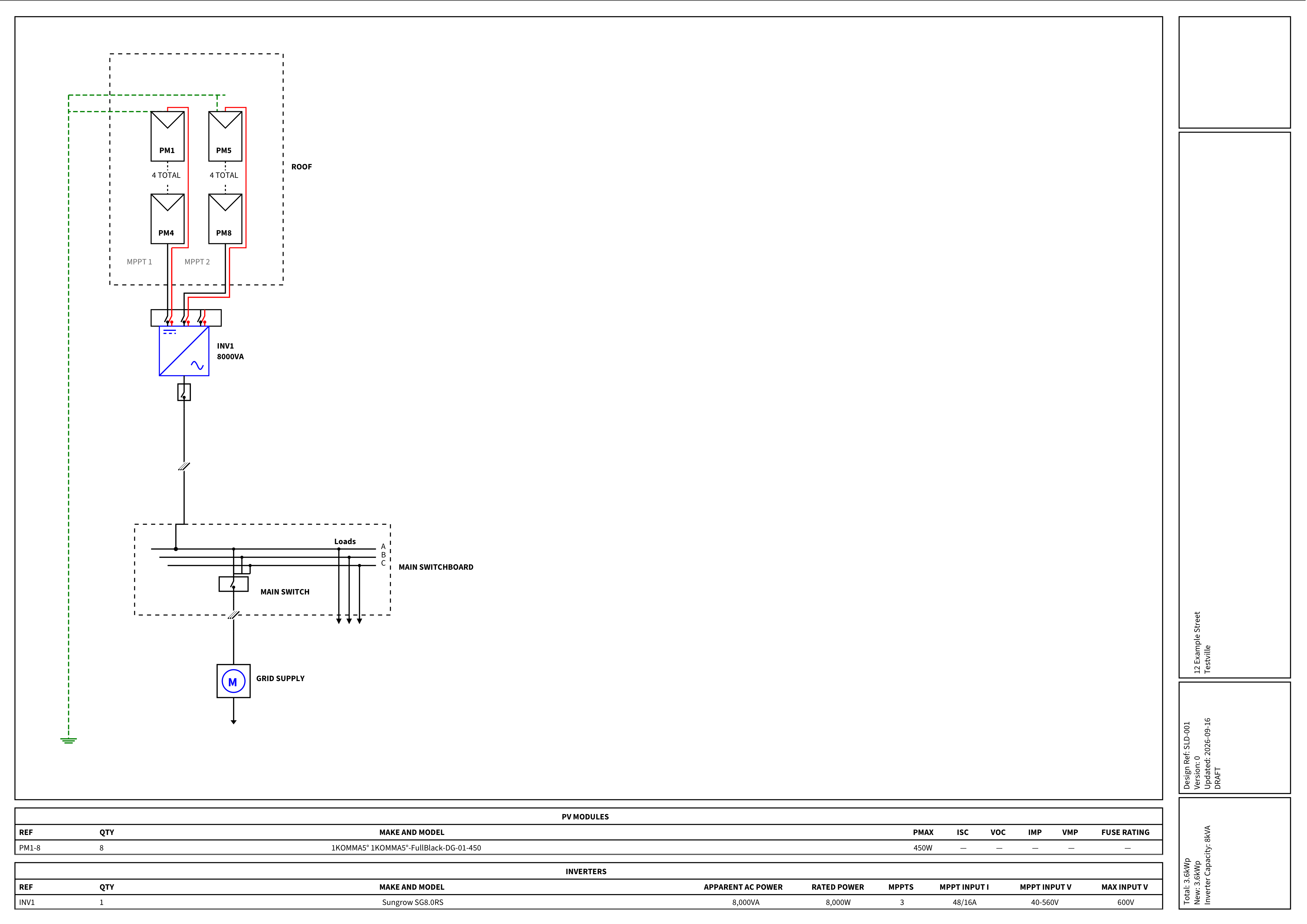
The exported A4 landscape project sheet, opened from a roof design — the record of the drawing, in the file the editor names `single-line-diagram.pdf`. Its **PV MODULES** and **INVERTERS** schedules sit below the drawing, and the rail beside it carries the address, design ref, version, date and `DRAFT` status. It is a draft of declared connectivity, not a certified drawing.
single-line-diagram.pdf file it produces is the one you file with the job.This is a design drawing, not a certified one. It shows the connectivity you declared. It does not certify that a real switchboard is safe or correct, and it does not simulate how a manufacturer’s protection device behaves.
Related
- Design the roof and the panels — the roof layout the diagram is built from.
- Stringing — the strings that seed the initial diagram.
- Use Roof Design — how the design reaches the quote.
- Roof design integration contract — routes, assets, permissions and error codes.
- Field operations — what the installer receives and does.